

Use recommended warning signs. All 737-300/-400/-500 and Next-Generation 737 airplanes at delivery have Boeing-applied hazard area red warning stripes, above-idle hazard area decals, and no-entry decals applied to the engine nacelles (see fig. 3). Similar hazard area warning stripes and decals were also applied to all 737-100/-200 airplanes beginning with Line Position 1020, which was delivered in May 1984. For 737-100/-200 airplanes prior to Line Position 1020, hazard area warning stripes and decals can be applied per Boeing Service Bulletin 737-11-1010 Revision 1, dated June 21, 1985.
HAZARD-AREA WARNING DECALS
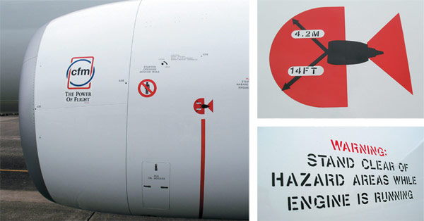
Figure 3
These hazard-area warning decals are located on both left and right engine nacelles. For the 737, hazard-area warning stripes and decals have been applied to all CFM56 engine nacelles prior to delivery. Inlet hazard-area warning stripes and decals were applied to all JT8D engine nacelles prior to delivery beginning with airplanes delivered in May 1984. Boeing Service Bulletin 737-11-1010, Revision 1, dated June 21, 1985, provides for retrofit application of warning stripes and decals on JT8D engine nacelles delivered prior to this date.
To further promote awareness of engine inlet hazard zones and provide ground personnel with a visual definition of the zones, some operators have painted engine inlet hazard zone boundaries on ramp surfaces at parking locations. If ramp surfaces are painted, Boeing recommends only painting hazard boundaries for above idle power to prevent any confusion that may result from different boundary areas. Operators also need to be aware that different hazard boundaries exist for 737-100/-200/-300/-400/-500 than for Next-Generation 737 airplanes. Any painted ramp surfaces should reflect the larger above idle power Next-Generation 737 hazard boundary area if operators have multiple 737 derivatives in their fleets. Procedures should be established to ensure that airplanes are correctly parked in relation to the painted hazard zone boundary so that the inlet reference point of each engine is within the recommended tolerance. Additional information regarding hazard boundaries painted on ramp surfaces can be found in Boeing Service Letter 737-SL-71-028A, dated April 25, 2002.
Communicate the dangers of working near operating engines and institute and enforce safe procedures. Operators should emphasize the need for ground personnel to be constantly aware of the engine hazard zones and clearly communicate that carelessness near an operating engine inlet can be fatal. Operators should also emphasize that when ramp surfaces are slippery near the inlet hazard zone boundary, additional precautions, such as cleaning the ramp, will be necessary to provide for worker safety. In addition, if surface winds are gusty and greater than 25 knots, the dimensions defining the inlet hazard zone boundary should be increased by 20 percent.
If it is necessary for ground personnel to be near the engine during an engine operation (such as during an idle leak check or to disconnect the ground air cart), they should make sure that the engines are at minimum idle and use only the entry/exit corridor to enter and exit the fan case area (see fig. 4 for Next-Generation 737 airplanes). Similar 737-100/-200/-300/-400/-500 entry corridors are identified in the applicable AMM. Inlet screens and a Boeing-approved personnel safety harness (part number F8023912) can be used for additional protection. Correct use of the safety harness is described in the AMM.
737 ENTRY/EXIT CORRIDORS
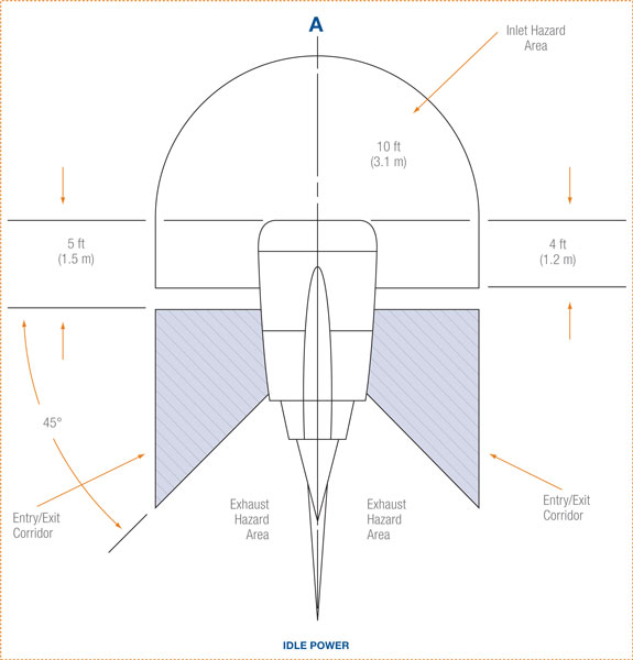
Figure 4
Ground personnel must use only the designated entry/exit corridor when it is necessary to be near an operating engine. (The Next-Generation 737 is shown; 737-100/-200/-300/-400/-500 entry corridors are similar.)
[+] Enlarge