
ENGINE AND APU START
The 787's engine-start and APU-start functions are performed by extensions of the method that has been successfully used for the APU in the Next-Generation 737 airplane family. In this method, the generators are run as synchronous starting motors with the starting process being controlled by start converters. The start converters provide conditioned electrical power (adjustable voltage and adjustable frequency) to the generators during the start for optimum start performance.
Unlike the air turbine engine starters in the traditional architecture that are not used while the respective engines are not running, the start converters will be used after the respective engine is started. The engine- and APU-start converters will function as the motor controller for cabin pressurization compressor motors.
Normally, both generators on the APU and both generators on the engine are used for optimum start performance. However, in case of a generator failure, the remaining generator may be used for engine starting but at a slower pace. For APU starting, only one generator is required.
The power source for APU starting may be the airplane battery, a ground power source, or an engine-driven generator. The power source for engine starting may be the APU generators, engine-driven generators on the opposite side engine, or two forward 115 VAC ground power sources. The aft external power receptacles may be used for a faster start, if desired.
ENVIRONMENTAL CONTROL SYSTEM
In the 787 electrical architecture, the output of the cabin pressurization compressors flows through low-pressure air-conditioning packs for improved efficiency. The adjustable speed feature of electrical motors will allow further optimization of airplane energy usage by not requiring excessive energy from the supplied compressed air and later regulating it down through modulating valves resulting in energy loss.
Avoiding the energy waste associated with down regulation results in improvements in engine fuel consumption, and the environmental-control-system air inflow can be adjusted in accordance with the number of airplane occupants to achieve the lowest energy waste while meeting the air-flow requirements.
WING ICE PROTECTION
In the traditional architecture, hot bleed air is extracted from the airplane bleed system and distributed through the areas of the wing leading edge that need ice protection. For each wing, one valve controls the flow of the bleed air to the wing leading edge, while a "piccolo" duct distributes the heat evenly along the protected area of the wing leading edge. In addition, should ice protection on the leading edge slats be required, a telescoping duct supplies bleed air to the slats in the extended position. The spent bleed air is exhausted through holes in the lower surface of the wing or slat.
The 787 utilizes an electro-thermal ice protection scheme, in which several heating blankets are bonded to the interior of the protected slat leading edges. The heating blankets may then be energized simultaneously for anti-icing protection or sequentially for deicing protection to heat the wing leading edge. This method is significantly more efficient than the traditional system because no excess energy is exhausted. As a result, the required ice protection power usage is approximately half that of pneumatic systems. Moreover, because there are no-bleed air exhaust holes, airplane drag and community noise are improved relative to the traditional pneumatic ice protection system.
APU
As in a traditional architecture, the APU in the no-bleed electrical architecture is mounted in the airplane tail cone, but it provides only electrical power. Consequently, it is much simpler than the APU for the traditional architecture because all of the components associated with the pneumatic power delivery are eliminated. This should result in a significant improvement in APU reliability and required maintenance.
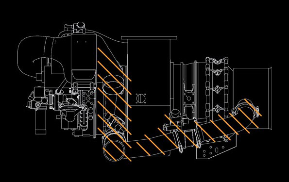
Figure 4 shows the APU for a 767-400 airplane, identifying the pneumatic portions that will be eliminated in a no-bleed electrical architecture. Moreover, taking advantage of the variable frequency feature of the 787 electrical system, the APU operates at a variable speed for improved performance. The operating speed is based on the ambient temperature and will be within a 15 percent range of the nominal speed.
Figure 4
This diagram of an APU for a 767-400 airplane shows the pneumatic portions that will be eliminated in a no-bleed architecture.
SUMMARY
A key benefit expected from the Boeing 787's no-bleed architecture is improved fuel consumption as a result of more efficient engine cycle and more efficient secondary power extraction, power transfer, and energy usage.
Eliminating the maintenance-intensive bleed system is also expected to reduce airplane maintenance needs and improve airplane reliability because there are fewer components on the engine installation; there are no IDGs, pneumatic ducts, pre-coolers, valves, duct burst protection, and over-temperature protection; and there is no compressed air from the APU, resulting in a simplified and more reliable APU.
The 787 no-bleed architecture also features modern power electronics and motors that will provide increased overall reliability, decreased costs, and improved performance. Finally, the architecture means reduced airplane weight, reduced part count, and simpler systems installation. For more information, please contact Lori Gunter at loretta.m.gunter@boeing.com.
