HYDRAULIC SYSTEM
The hydraulic system in the 787 no-bleed architecture is similar to the one in the traditional architecture. There are three independent systems — left, center, and right — that collectively support primary flight control actuators, landing gear actuation, nose gear steering, thrust reversers, and leading/trailing edge flaps.
The primary power source for the left and right systems are engine-driven pumps mounted on the engine gearbox. In addition, the left and right systems are each powered by an electric-motor-driven hydraulic pump for peak demands and for ground operations.
The key difference between the traditional and 787 hydraulic system is the power source for the center system. In the traditional architecture, the center system is powered by two large air-turbine-driven hydraulic pumps, which operate at approximately 50 gallons per minute (gpm) at 3,000 pounds per square inch (psi) to meet peak hydraulic demands for landing gear actuation, high lift actuation and primary flight control during takeoff and landing. During the remainder of the flight, two small (approximately 6 gpm) electric-driven hydraulic pumps power the center system.
In the 787 no-bleed architecture, the center hydraulic system is powered by two large (approximately 30 gpm at 5,000 psi) electric-motor-driven hydraulic pumps. One of the pumps runs throughout the entire flight and the other pump runs only during takeoff and landing. The higher pressure of the 787's hydraulic system enables the airplane to use smaller hydraulic components, saving both space and weight.
ELECTRICAL SYSTEM
The 787 uses an electrical system that is a hybrid voltage system consisting of the following voltage types: 235 volts alternating current (VAC), 115 VAC, 28 volts direct current (VDC), and ±270 VDC. The 115 VAC and 28 VDC voltage types are traditional, while the 235 VAC and the ±270 VDC voltage types are the consequence of the no-bleed electrical architecture that results in a greatly expanded electrical system generating twice as much electricity as previous Boeing airplane models. The system includes six generators — two per engine and two per APU — operating at 235 VAC for reduced generator feeder weight. The system also includes ground power receptacles for airplane servicing on the ground without the use of the APU.
The generators are directly connected to the engine gearboxes and therefore operate at a variable frequency (360 to 800 hertz) proportional to the engine speed. This type of generator is the simplest and the most efficient generation method because it does not include the complex constant speed drive, which is the key component of an integrated drive generator (IDG). As a result, the generators are expected to be more reliable, require less maintenance, and have lower spare costs than the traditional IDGs.
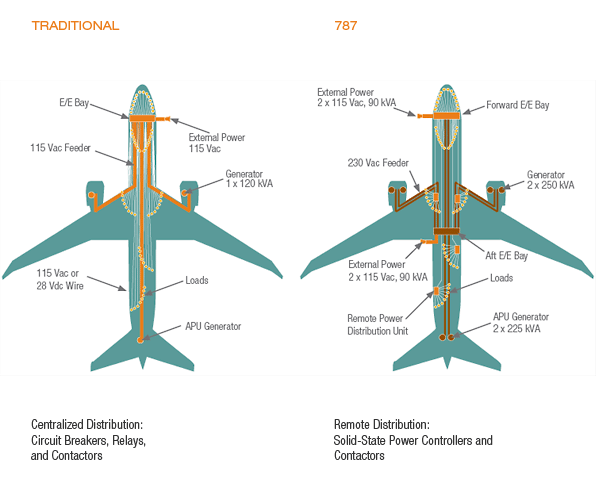
The electrical system features two electrical/electronics (E/E) bays, one forward and one aft, as well as a number of remote power distribution units (RPDU) for supporting airplane electrical equipment. The system saves weight by reducing the size of power feeders. A limited number of 235 VAC electrical equipment is supplied from the aft E/E bay, while the majority of airplane electrical equipment, being either 115 VAC or 28 VDC, are supported by the forward E/E bay and RPDUs as shown schematically in figure 3. The RPDUs are largely based on solid-state power controllers (SSPC) instead of the traditional thermal circuit breakers and relays. The ±270 VDC system is supplied by four auto-transformer-rectifier units that convert 235 VAC power to ±270 VDC. The ±270 VDC system supports a handful of large-rated adjustable speed motors required for the no-bleed architecture. These include cabin pressurization compressor motors, ram air fan motors, the nitrogen-generation-system compressor used for fuel-tank inerting, and large hydraulic pump motors.
The system, as shown in figure 3, features two forward 115 VAC external power receptacles to service the airplane on the ground without the APU and two aft 115 VAC external power receptacles for maintenance activities that require running the large-rated adjustable speed motors.
The 787's electrical system uses a remote distribution system that saves weight and is expected to reduce maintenance costs.


