AIRPLANE STRUCTURAL CAPABILITY
Overweight landings are safe because of the conservatism required in the design of transport category airplanes by FAR Part 25.
FAR criteria require that landing gear design be based on:
- A sink rate of 10 feet per second at the maximum design landing weight; and
- A sink rate of 6 feet per second at the maximum design takeoff weight.
Typical sink rates at touchdown are on the order of 2 to 3 feet per second, and even a “hard” landing rarely exceeds 6 feet per second. Additionally, the landing loads are based on the worst possible landing attitudes resulting in high loading on individual gear. The 747-400 provides an excellent example. The 747-400 body gear, which are the most aft main gear, are designed to a 12-degree nose-up body attitude condition. In essence, the body gear can absorb the entire landing load. The wing gear criteria are similarly stringent: 8 degrees roll at 0 degrees pitch. Other models are also capable of landing at maximum design takeoff weight, even in unfavorable attitudes at sink rates up to 6 feet per second. This is amply demonstrated during certification testing, when many landings are performed within 1 percent of maximum design takeoff weight.
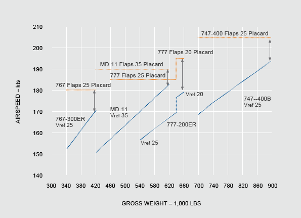
When landing near the maximum takeoff weight, flap placard speeds at landing flap positions must be observed. Due to the conservative criteria used in establishing flap placard speeds, Boeing models have ample approach speed margins at weights up to the maximum takeoff weight (see fig. 1).
UP TO MAXIMUM TAKEOFF WEIGHT
Boeing Models with Fuel Jettison Systems
Figure 1

In addition to specifying a maximum landing weight, the FAA-approved airplane flight manual (AFM) for some 747-400 and MD-11 airplanes includes a limitation on the maximum in-flight weight with landing flaps. This weight is conservatively established to comply with FAR 25.345, flaps down maneuvering to a load factor of 2.0. Compliance with FAR 25.345 is shown at a weight sufficiently above the maximum design landing weight to allow for flap extension and maneuvering prior to landing. Because the loads developed on the flaps are primarily a function of airspeed and are virtually independent of weight, the flaps will not be overstressed as long as airspeed does not exceed the flap placard speed.
If the maximum in-flight weight with landing flaps is exceeded, no special structural inspection is required unless the flap placard speed or the maximum landing weight is also exceeded. Generally, if the maximum in-flight weight with landing flaps is exceeded, the maximum design landing weight will also be exceeded and, by definition, an overweight landing inspection will be required.
Loading on the basic wing structure due to increased landing weight can be controlled by limiting the bank angle. To maintain reasonable structural margins, Boeing recommends that operating load factors be limited to those corresponding to a stabilized 30-degree banked turn.
All Boeing airplanes have adequate strength margins during overweight landings when normal operating procedures are used, bank angle does not exceed 30 degrees, and flap placard speeds are not exceeded.
AIRPLANE PERFORMANCE CAPABILITY
Increased gross weight can have a significant effect on airplane performance. Whenever possible, it is strongly recommended that normal FAR landing performance margins be maintained even during overweight landing. The AFM typically provides landing performance data at weights significantly above the maximum design landing weight and can be used in conjunction with landing analysis programs to calculate landing performance.
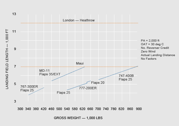
The landing field length capability of Boeing airplanes is such that, even ignoring reverse thrust, excess stopping margin is available at weights well above the maximum design landing weight (see fig. 2). The data in figure 2 are based on a dry runway with maximum manual braking. Wet and slippery runway field-length requirements, as well as autobrake performance, should be verified from the landing distance information in the performance section of the flight crew operations manual (FCOM) or quick reference handbook (QRH).
UP TO MAXIMUM TAKEOFF WEIGHT
Figure 2


