LIMITATIONS WITH PRINTED DIAGRAMS
Traditional printed wiring diagrams were contained in a Wiring Diagram Manual (WDM) that provided airline maintenance teams with a precise representation of an airplane’s wiring system. However, the process of locating the exact wiring harness, junction, wire, or other electrical component takes time away from the mechanic’s real job: fixing a problem so the airplane can return to service. The data presented in the WDM was static and was not capable of data sorting or data linking.
It can also be a very time-consuming process — an electrical wiring manual may have 75 pages between a line replaceable unit and its associated connector. When assessing an electrical fault, the airline maintenance team must look through each of those pages to identify the WDM diagram pages that are applicable to the airplane tail number.
Additionally, when an airplane’s electrical system has been modified, updated diagrams must be printed and distributed.
MAKING WIRING DIAGRAMS DYNAMIC
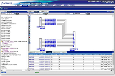
The new electronic Schematic and Wiring Analysis Tool/Integrated Wiring Suite (eSWAT/IWS) that Boeing has developed for the 787 eliminates the production of a printed manual and enables airline maintenance teams to spend less time doing analysis and more time doing maintenance by providing flexible, dynamic wiring diagrams with customizable views. That, in turn, helps ensure efficient, high-quality repairs.
Users can adjust the view of the wiring diagram to see the entire airplane wiring system or a single wire path from power to ground (see fig. 1). Users can also adjust the view to better understand and orient the diagrams of the airplane’s configuration and highlight any wire or harness in a specific color to make it easier to follow the wiring from source to termination. Other functionality includes links to other information as well as ties between visual wiring diagrams and wiring data reports. The application also allows for the linking of operator-specific supplemental data to the Boeing data structure. These features enable maintenance personnel to quickly understand and work with the electrical configurations in the 787.


